
About the author
Werner Muller loved to tinker with electronics since he was a younster. Currently he enjoys SSB and CW contacts and satellites. He built a setup for an QO-100 geostationary satellite and have over 100 countries confirmed via this satellite. Recently Low Earth Orbiting (LEO) satellites started to interest him as well. He is a licensed amateur radio operator and the current President of the Namibian Amateur League. His callsign is V51JP.
How it started
After being on the air with QO-100 for a few years now I suddenly developed an itch to try something new. Working with LEO satellites started to fascinate me some time ago but I had no idea how it worked. So I did the next best thing, I started collecting stuff I thought I needed. First I bought a second hand azimuth rotor, next a couple of antennas for 70cm and most recently I was offered an elevation rotor. This triggered my curiosity and I started asking the cleverest person I know a lot of silly questions. Mrs Google was very informative and soon I knew what I needed. A tracker that could follow the satellite with the help of some software. I researched this topic for a while and soon found that it was not as difficult as I thought. Everything I needed was available here in Windhoek!
How to build a controller for a LEO satellite station
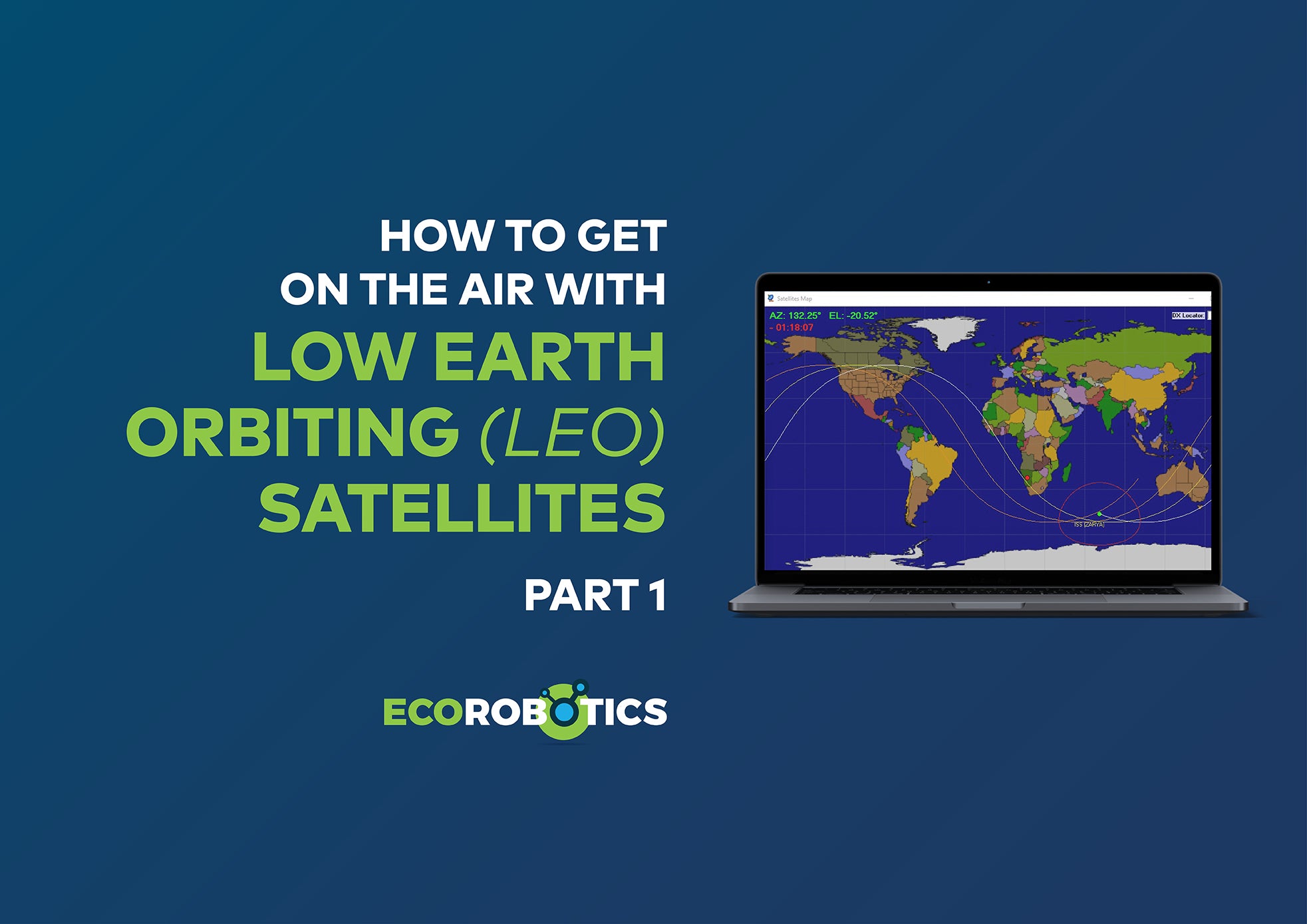
For part 1 I am going to take you through the steps to build a controller for a LEO satellite station.
Here is the list of everything I needed:
1x Arduino UNO
1x 8 Relay output board
1x 16x4 display
1x buck converter 12v to 5v
1x bread board
1x set Dupont jumper wires
2x rotary encoders
2x 1k potentiometers
A housing of some sort

I started by downloading a sketch from https://create.arduino.cc/projecthub/viorelracoviteanu/antenna-rotator-controller-compatible-with-tracking-software-48f9cd and checked what I had to change to suit my personal needs. Firstly the sketch was for a 90 deg rotor, mine is a 180 deg rotor. The sketch was done for a 16x2 display. I wanted two extra rows for my callsign and the grid locator so I had to adapt the sketch for that.
With the sketch compiled I uploaded it to the Arduino and connected a crow’s nest of wires to everything and started testing. Everything worked and I started thinking about a housing. All my project boxes where to small so I opted for an custom box. This was laser cut, CNC bent and powdercoated.

Assembling all the hardware into the enclosure was super easy as all the holes for the standoffs had been laser cut.

I had issues with the 5V supply from the Arduino, it was just not enough so I installed a DC to DC converter to power the relay board.

Next I printed knobs on a 3D printer.

At this time I completed the wiring for the rotators and the Arduino and tested the system again.


I set the controller up with the potis simulating the rotors and connected everything to the PC via USB.

The last step was to get the rotors hooked up and the internal potentiometers calibrated to the controller.
For additional information:
Werner Mullerkavanji.wm@gmail.com
Call sign: V51JP
If you want to learn more about the fascinating Radio Amateur Hobby please visit: https://www.narlnam.com
4 comments
Stephan - V51SH
Very Awesome Project. Might have a look at it as well if I have more time avaliable! First needs to start like Werner and gather more info on the parts. :)
Robert V51RS
Nina DL2GRC - VK2INZ
Congratulaziins Werner, great Job well done!
Looking for a contact with you someday, but we probably need MEO :-)
73s de Nina
Martin DL1ZU - V51ZU - K1ZU
Wow! Well done!
Thats pretty cool 😎
73,
Martin